


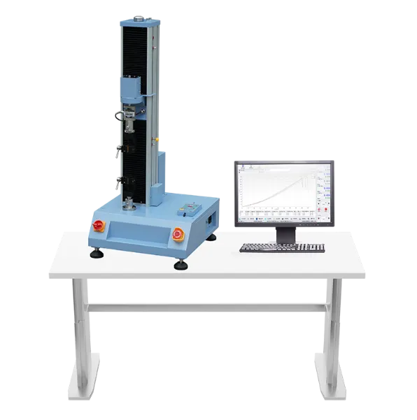
If a mechanical testing machine passes its daily check and the tensile numbers still get challenged in a design review, the frame is almost never the culprit. The gap sits in the interface between the material and the machine — the grips, the fixtures, the alignment, and the way the specimen is seated in them. Across more than a decade of commissioning benches, we have spent far more hours chasing scatter in an elongation value than we have ever spent repairing a load cell, and the root cause was usually a worn jaw insert or a grip body that nobody treated as part of the measurement chain.
This guide follows the order we use when a new bench is qualified, not the order a tooling catalogue is written in. We will cover five steps in sequence: decide where the specimen is allowed to break, choose the holding method that produces that break, lock down alignment and stiffness, mount the extensometer and control specimen geometry, and finally set up bend and compression tooling, which obeys entirely different rules. After that we will look at the frame details that decide whether any of it can be repeated next month.
The short version, if you only read this far
- Write down the failure location first. The holding method follows from it.
- Clamping force is the least useful number in a grip decision. Stiffness and alignment decide whether the result survives review.
- Alignment and stiffness errors never warn you. They only surface when someone rebuilds your setup.
- Bend and compression fixtures are geometry problems, not hardware problems.
Step 1: Decide Where the Specimen Should Break Before You Touch Any Tooling
Every holding decision becomes obvious once you write down where the specimen is allowed to fail. A tensile result is a property of the material only if the break happens inside the gauge length, away from both grips. If it keeps failing at the jaw, the number describes your bench, not the alloy.
| Where it breaks | What the number actually describes | Correct response |
|---|---|---|
| Inside the gauge length | The strength and ductility of the material itself | Keep the hold as gentle as the material allows and record it |
| At the jaw face | The clamping system, plus whatever stress concentration the teeth created | Change the jaw insert or the pressure, then re-run the set |
| In the shoulder or fillet | Specimen preparation, not the tooling | Fix the specimen geometry; leave the grips alone |
| Outside the extensometer span | A partial curve with an unusable last third | Move the gauge length or reposition the arms |
Only the first row gives you a number you can defend, and in our experience most labs can name the target failure location but have never written it into the method. Do that first. Once the target failure location is written down, the next question is which holding method can actually produce it.
Step 2: Choose the Holding Method From the Material and the Force Band
Pick the grip by what the specimen needs at the moment of failure, not by what the frame can push. Wedge, hydraulic, pneumatic and wrap style holders each control a different variable, and the most common mistake we see is reaching for the strongest option when the material wants the gentlest one.
| Holding method | Best fit | Where it belongs in the load range | Typical watch out |
|---|---|---|---|
| Wedge, self tightening | Stiff metals, rigid polymers, machined coupons | Light work up through heavy work, it grows with the load | Jaw bite marks and shoulder breaks on softer material |
| Hydraulic | Heavy metal sections, repetitive production runs | Mid to heavy work, where hand clamping is impractical | Pressure drift and seal maintenance |
| Pneumatic | Thin sheet, soft samples, high volume testing | Light work, where pressure must be repeatable rather than high | Slipping when the pressure is set too low for the sample |
| Wrap or capstan | Wire, yarn, film and tape, anything that would crush in a jaw | Light work, where the specimen must never be clamped directly | Wrong wrap angle and uneven tension between the two ends |
Two symptoms send most people back to the catalogue: the specimen slides, or it breaks at the jaw. In our experience both have a short list of causes, and none of them is the frame.
- A jaw face that is too hard or too fine for the material, so the teeth cannot bite and the peak simply flattens.
- Clamping pressure set light enough to protect a soft sample, then reused on a stiffer one that needs more grip.
- Specimen ends cut too short or not parallel, so the grip closes on a taper and loads one edge first.
- Polished or worn inserts that have run thousands of specimens and no longer hold evenly along the face.
- A self tightening holder on soft material, gripping harder as the load rises and crushing the shoulder before the material reaches its strength.
The rule we give customers is short: if the specimen keeps breaking at the jaw and the material is not supposed to be brittle, change the interface before you change the machine. A holding method that produces the right failure location still leaves one silent question open, which is whether the load arrives along the axis you think it does.
Step 3: Lock Down Alignment and Stiffness, Because a Reviewer Rebuilds That Part First
Stiffness and alignment are the errors that never announce themselves. They do not trip a limit, they do not appear on a single channel chart, and they quietly pull the failure away from where the material wants it to happen. When we verify a fixture set, these are the four items we check every time: fixture stiffness under load, alignment of the load string, concentricity of the specimen, and the length of the adapter stack between the sensor and the grip.
This is where a frame specification stops being a datasheet detail. On our frames the crossbeam is cut from 45# die steel and held to a parallelism error of no more than 0.5 mm, the moving platen travels on four column chrome plated steel guide rods, and the force path runs through high precision ball screws driven by a Panasonic servo motor. Each detail protects a different part of the result.
| Design detail | Published figure | What it protects in your result |
|---|---|---|
| Crossbeam material and parallelism | 45# die steel, parallelism error ≤0.5 mm | Keeps the two grip axes parallel, so the specimen does not see bending on top of tension |
| Four column guidance | Chrome plated steel guide rods on four columns | Stops the moving platen from tilting as it travels, which would swing the load line |
| Drive system | High precision ball screws, Panasonic servo motor | Repeatable crosshead motion instead of a jump at the start of the run |
| Force sensor | TRANSCELL load cell, accuracy 0.03% F.S. | Makes the force channel the least of your worries, and lets you look elsewhere |
A parallelism error of half a millimetre sounds negligible until you remember that it is measured at the platen. A small tilt at the platen becomes a larger offset at the specimen ends, and an offset at the ends is a bending moment. A specimen loaded in tension plus bending fails earlier, and often in an unexpected place, for reasons that have nothing to do with its chemistry. That is why we publish the number instead of writing high rigidity and moving on, and it is the reason we describe the mechanical testing machine range as a load path rather than a list of parts.
If alignment is in doubt, it can be measured rather than argued about. A strain gauged alignment specimen, or a simple set of repeat runs with the specimen rotated through a quarter turn, will tell you whether an offset is real. That evidence is far more persuasive than a note saying the machine was checked and looks fine. With the load path straight, the next question is how you measure the deformation that happens along it.
Step 4: Mount the Extensometer and Hold Specimen Geometry to Tolerance
An extensometer measures the specimen, but a badly mounted extensometer measures the fixture. Clip on arms that bridge the jaw, knife edges that bite into a soft surface, or a gauge that shifts as the sample necks all produce a signal that looks like real strain data. After grip seating, this is the second largest source of dispute we see, and almost all of it is preventable.
- Set the gauge length on the specimen itself, never on the grip body, and record the value you actually used rather than the nominal one.
- Confirm the arms are free and fully seated before the run starts. A slightly open arm reads a stiff specimen as a soft one.
- Watch for slip at the knife edges. If the reading jumps early, the arms are tracking the surface instead of the deformation.
- Keep the gauge clear of the failure zone. If the break happens under the arms, the last third of the curve is meaningless.
Resolution matters here, because it decides whether the early part of the curve is real data or rounding. On our Model B electronics the displacement resolution is 0.015 µm, and on Model A it is 0.001 mm, with a displacement indication error of ±0.2% on Model B and ±0.5% on Model A. In plain terms, an elastic region that would look like a straight line on a coarser system separates into a readable slope, so the modulus you report can be traced back to a genuine measurement. Force resolution is just as relevant: Model B resolves 1 in 500,000 of full scale across the whole range with no range switching, against 1 in 200,000 on Model A, which means a small drop just before failure does not disappear into the display.
Specimen geometry is the other half of this step. A machined coupon that is 0.05 mm thin on section is a different cross section, and the stress you calculate will be off by roughly that fraction. For moulded or cast samples, flash left along the edge acts as a stress raiser and pulls the break out of the gauge length. Neither problem shows up in the force channel, and both are obvious in a dimension record taken before the run. When the specimen also has to sit inside a temperature chamber, the fixture problem changes again: a universal testing machine with temperature chamber has to hold alignment while pull rods cross a thermal boundary and change length with heat. Tension is only one of the test types a bench has to serve, and the remaining ones abandon the grip altogether.
Step 5: Treat Bend and Compression Tooling as Geometry, Not Hardware
Flexure and compression do not fail at the grip, so the errors move to the supports and the platens. Here the geometry you choose is the test. Change the span or the contact radius and you change the stress field, which is why two labs can run the same material to the same document and report different numbers.
Support span and roller radius
In three point bending the span is a controlled parameter, not a convenience. A wide span loads a longer section and is more sensitive to internal flaws; a narrow span concentrates stress and is more sensitive to surface condition. Roller radius matters too, because a small roller creates local indentation that the material feels as a stress raiser. When a design review compares two sets of flexural data, the first question we ask is whether the spans and the rollers matched.
Platen seating and centring
Compression is unforgiving about seating. If the platens are not parallel or the cut face is not flat, the load arrives on one edge first and the specimen shears or splits instead of compressing. Self aligning platens help, but they do not correct a specimen that was cut at an angle. For soft or porous material we use a small documented preload to settle the faces before the measurement zone begins, so the setup can be repeated by anyone on the shift. Centring matters just as much as parallelism, because a cube placed off centre in a two platen setup is being tested in bending whether you intended it or not.
That completes the five decisions in the order we run them. They are also the order in which a reviewer will take your file apart, so the working notes from each step are worth keeping together. The guide to mechanical testing machines covers the frame side of that story, and if your work is dominated by one test type then the tooling questions get narrower. A single frame with a documented family of interchangeable fixtures is what most of our customers settle on, because the setup sheet then travels with the test instead of living in one operator's memory. That is the configuration behind our electronic universal testing machine platform, and it is the same logic that keeps an environmental tensile tester aligned while the specimen sits at temperature.
One more thing worth writing into the method: the control mode. A single bench has to serve seven test types — tension, compression, bend, peel, puncture, friction and shear — across force capacities of 100 kN, 300 kN and 600 kN, and against GB, ISO, JIS, ASTM and DIN documents. Constant stress, constant strain and constant displacement control each hold a different variable fixed, and a specimen that creeps during a hold will report a different result under each one. Our automotive application work is where this becomes most visible, because a fastener alloy tested at constant stress and at constant strain rate produces two curves that a supplier and a customer can argue about for a week.
Frequently Asked Questions About Your Mechanical Testing Machine Setup
Do I need a different grip for every material?
Not necessarily, but you do need a jaw face and a pressure setting chosen for the material class. One grip body often covers several materials if you change the insert and record the pressure. What you cannot do is run stiff metal and thin sheet through the same jaw face at the same pressure and expect both results to be valid.
How can I tell if my fixture is too compliant?
Compare the displacement you commanded with the extension the extensometer recorded on a stiff specimen. If the crosshead travelled noticeably farther than the specimen stretched, some of that travel went into the fixture. A compliant setup also tends to under report modulus and to show early nonlinearity in the loading curve.
Is it acceptable to discard specimens that break at the jaw?
The document you are working to defines valid and invalid failures, so follow that first. But if jaw breaks are common, treat them as a signal about your tooling rather than a routine filter. A setup that routinely throws results away is telling you something about the interface, and a reviewer will notice the discard rate even when each individual discard was permitted.
How often should grips and fixtures be inspected?
Base the interval on how hard the tooling works, not on a calendar habit. High throughput lines need frequent checks of insert wear and seating position. Low volume labs can go longer. What matters is that the inspection is written down and that a worn insert is replaced before it starts shaping results rather than after.
Matching grips and fixtures to a mechanical testing machine is not a purchasing detail. It is the step that decides whether your numbers describe the material or describe your bench. Get the load path straight, write the setup down, and keep the evidence that the test produced while it was running. Do that, and the next design review becomes a conversation about the specimen instead of an argument about the machine.
Build the load path once, then defend it for years
Check published parallelism, displacement resolution and force accuracy figures against the fixtures you plan to mount, so the interface stops being the weak link in a mechanical testing machine setup.
Review grips, fixtures and frame specs Send your material and test method